

Next: Further Reading
Up: Model Based Object Recognition
Previous: Relaxation Labelling Methods
- Object model and scene features are represented in a semantic network
based structure. In the original method by Nevatia and Binford they called
the network a relational graph structure:
- This method has been the basis of many popular ways of
representing and recognising objects in computer vision.
A graph consists of
- a
set of nodes connected by links (also called edges
or arcs).
- Each node represents an object feature (for example, a
surface)
- Nodes can be labelled with several of the feature's properties (such as
size, shape, area, compactness, type of surface etc.).
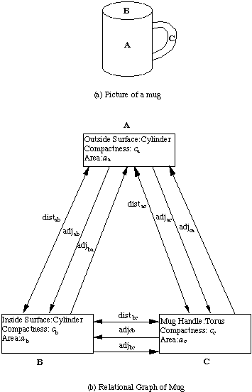
- Links of the graph represent relationships between features - e.g.
- Distance between centroids of the features,
-
Adjacency of the features -- the ratio of the length of
the common boundary between the two features to the
length of the perimeter of the first-named feature.
- Boundary
representation model can be represented as this kind of graph.
object.

Fig.  Picture of a mug and its simple graph representation
Note that some
relationships are two-way, such as distance, in that the relation does not
depend on the direction of the link.
Other relations, such as adjacency, do depend
on the direction.
Recognition:
- A matter of matching two graphs -- Graph of the object model to the graph
of the scene containing the object.
- Matching methods must take into account
occlusion and overlapping objects.
- A graph derived from a solid model of
the mug would contain the bottom which is missing from the view shown (and
scene model).
- So the problem is that of finding a
subgraph of the complete graph derived from the solid model.
- This is a large search space problem -- Use Constraints.
- Graph theory a big topic in its own right.
Let us return to consider how Nevatia and Binford perform their matching
strategy. They use a surface model with generalised cylinders as features,
arranged in a relational graph. The features are
collected into sets called ribbons which contain groups of
three-dimensional edges. Each group is hypothesised to form the boundary of a
single generalised cylinder.
A region where several
ribbon connect is represented by a joint . The representation
of each joint contains a list of connected ribbons. This
list is ordered, placing the longest or widest ribbons first. The longest
(or widest) ribbon is said to be distinguished.
For each view of the object a relational graph is constructed with joints as
nodes, and with links corresponding to associated ribbons. These links store various
geometric properties of the ribbons, including axis length,
average cross-section width, elongation and class (cone or
cylinder).
The graph representing the view is then matched to the model description in two
steps:
- For each distinguished ribbon three properties are chosen to drive the
matching. These are:
- the connectivity of the ribbon,
- the type of the ribbon -- long or wide,
- the class of the ribbon -- conical or cylindrical.
Initial matches are sought by looking for distinguished features in the image. If
more than one match is found then the above properties are used to decide which
matches are most likely and hence should be considered first.
- The matches are then grown to include other ribbons so long as the consistency of
the connectivity relations is retained. A graph formed from a view is, however,
allowed to match the model graph if some ribbons in the model graph are not
present in the view. This amounts to finding subgraphs and allows for partial
occlusion.


Next: Further Reading
Up: Model Based Object Recognition
Previous: Relaxation Labelling Methods
dave@cs.cf.ac.uk

![]() Picture of a mug and its simple graph representation
Picture of a mug and its simple graph representation