

Next: Image processing
Up: 3D imaging
Previous: Methods of Acquisition
This Section describes the active stereoscopic subsystem which
provides the three-dimensional data to our system for
automatically inspecting mechanical parts.
NOTE: Whilst this Section considers some specific active
stereo problems, many of the other issues discussed are not
specific to any particular three-dimensional data acquisition
technique, and will be of general interest.
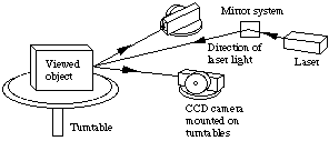
The main components of the Vision System are
illustrated by the schematic diagram in
Fig. 8.

Fig. 8 Schematic diagram of vision system
The vision system consists of:
- a matched pair of high sensitivity CCD cameras,
- a laser scanner all mounted on an optical bench to reduce
vibration.
Initially the cameras of the system must be calibrated in order
to
- determing the 3D position of them relative to some
world coordinates
- focal length and lens
distortion of the camera (+ lens etc.).
- Camera Calibration
is described in my book.
Depth maps extracted from the scene by :
- Moving the laser stripe across the scene to
obtain a series of vertical columns of pixels
- Triangulate Pixels
to give the required dense depth map. The depth of a point is
measured as the distance from one of the cameras, chosen as the
master camera.
- Knowing the relevant geometry and optical
properties of the cameras the depth map is constructed using the
following method:

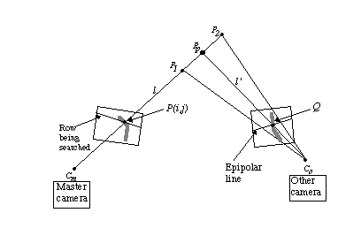
Fig. 9 Measuring a depth value
- For each vertical stripe of laser light form an image
of the stripe in the pair of frames from each
camera.
- For each row in the master camera image,
search until the stripe is found at point P(i,j), say.
- Form a three-dimensional line l passing through the centre
 of the master camera and P(i,j).
- Construct the epipolar line which is the projection
of the line l into the image formed by the other camera.
Do this by projecting two arbitrary points
 and
and  into
the image and constructing a line between the two projected
points.
- Search along the epipolar line for the laser stripe. If it
is found at
 , proceed to Step 6.
- Find the point
 on line l which corresponds to
 . Calculate the (x,y,z) coordinates of
  , and
store the z value at position (i,j) corresponding to x and
y in the depth map.
The position of the point  is easily found by
projecting a line
  from the centre
  of
the secondary camera passing through Q. The intersection of the
lines l and
  gives the coordinates of
  .
.
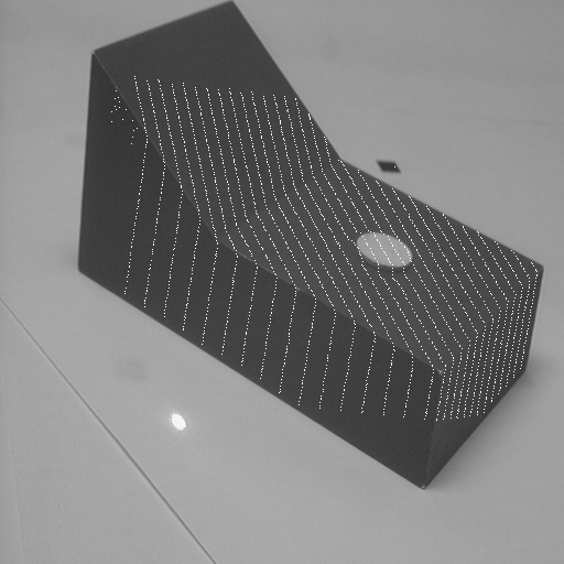
The depth map is formed by using a world
coordinate system fixed on the master camera with its origin at
 .
.

Fig. 10 Depth Map/Image Overlay


Next: Image processing
Up: 3D imaging
Previous: Methods of Acquisition
 David Marshall 1994-1997

![]() is easily found by
projecting a line
is easily found by
projecting a line ![]() from the centre
from the centre ![]() of
the secondary camera passing through Q. The intersection of the
lines l and
of
the secondary camera passing through Q. The intersection of the
lines l and ![]() gives the coordinates of
gives the coordinates of ![]() .
.
![]() .
.